Micro:bit Physical computing guides
No. 9: Ultrasonic sensor (HC-SR04 5v)
Connecting an Ultrasonic Sensor (HC-SR04 5v) to a micro:bit
Instructions on how to attach an Ultrasonic Sensor (HC-SR04 5v) to a BBC micro:bit.
Credit. Thanks to Ivan Holland for sharing how to power the HC-SR04 with a BBC micro:bit. You can view the original post here: https://www.makerspace-uk.co.uk/hc-sr04-ultrasonic-sensor/
Note: This guide is for the HC-SR04 5v. If you’re using the 3v3 tolerant version from Kitronik, click here.
What you will need
- BBC micro:bit
- Micro USB cable
- Battery pack with 2 x AAA batteries
- Battery pack with 3 x AAA batteries
- 1 x HC-SR04 (5v)
- 5 x Crocodile clip leads
Understanding Ultrasonic Sensors
The ultrasonic sensor works by sending out a high-frequency sound wave and calculating the time it takes for the signal to reflect back (echo).
The sensor has 2 openings on its front; one transmits an ultrasonic wave (transmitter) and the other receives the returning signal (receiver).
It works on the principle that sound travels approximately 341m/s in the air. Using this information, along with the time it takes to send and receive the sound wave, the ultrasonic sensor determines the distance to object using the equation:
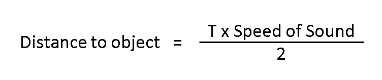
Where T = the time taken for the ultrasonic sensor to send and receive the sound wave.
The result is divided by 2 because the sound wave has to travel to the object and back.
The result is divided by 2 because the sound wave has to travel to the object and back.
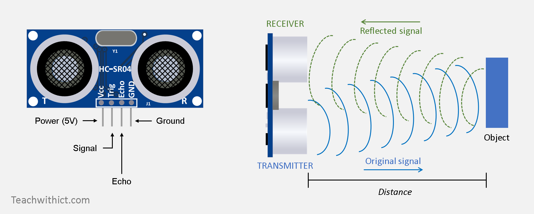
How an Ultrasonic Sensor works
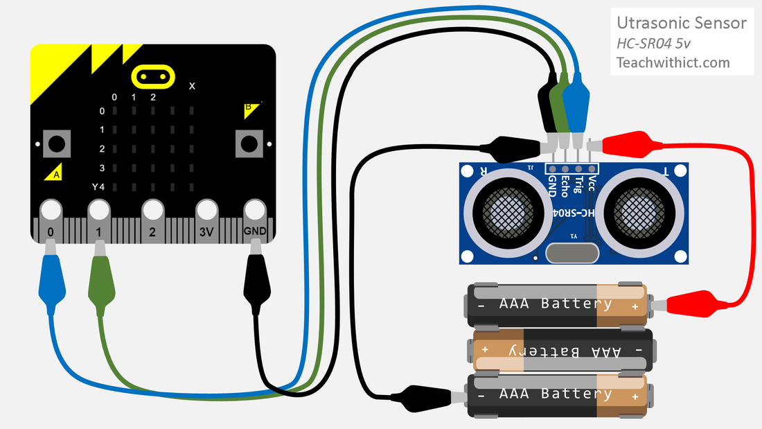
Wiring instructions
- Disconnect the micro:bit from your computer and disconnect the battery pack.
- Connect the crocodile clips to the corresponding pins:
- Trig to Pin 0.
- Echo to Pin 1.
- GND to GND.
- The HC-SR04 requires 5v to work, which is more than the 3.3 volts supplied by the BBC micro:bit. Fortunately, with the aid of a separate power source, it is possible to power the ultrasonic sensor using 3 x 1.5V (AA/AAA) batteries - thus providing 4.5V (sufficient to power the ultrasonic sensor). To connect the additional power source:
- Connect one crocodile clip from negative on the battery cage to GND on the micro:bit.
- Connect the remaining crocodile clip from positive on the battery cage to Vcc on the HC-SR04 ultrasonic sensor.
Programming your Ultrasonic Sensor
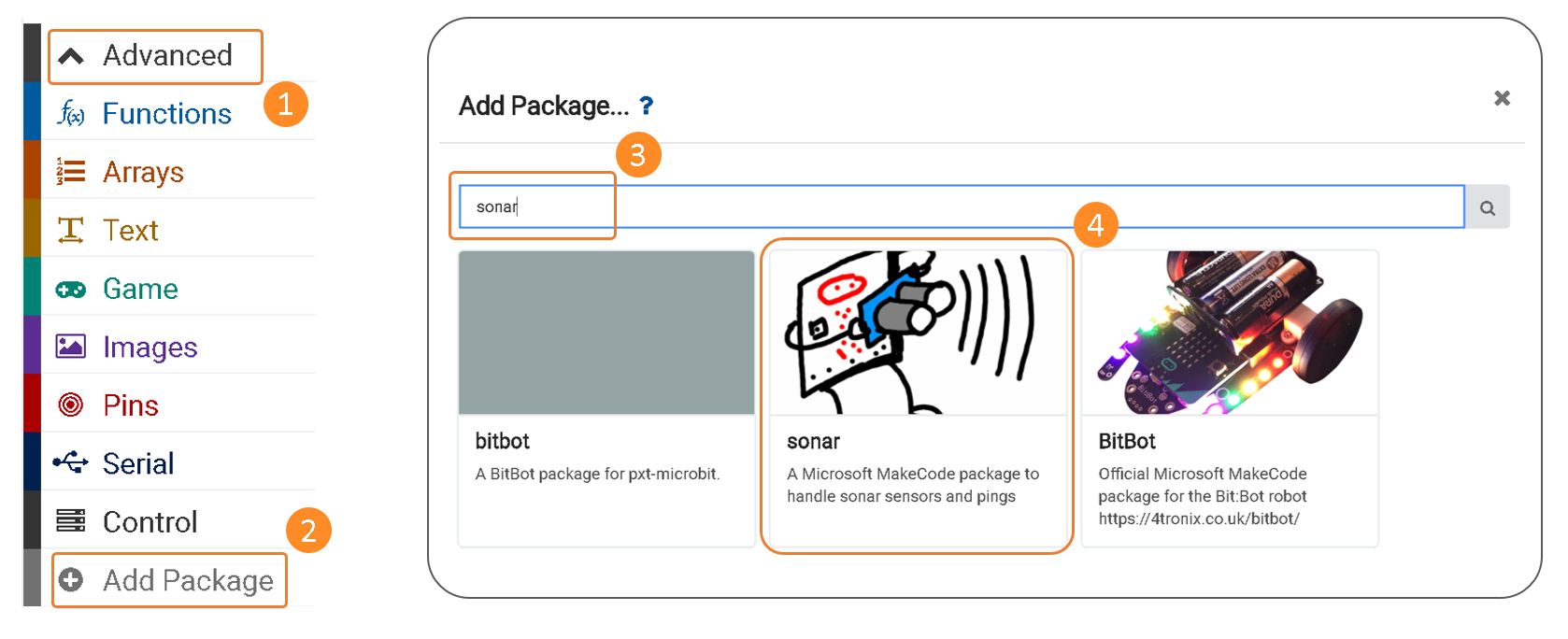
In order to program the ultrasonic sensor, you will need to add the Sonar package:
Programming your Ultrasonic Sensor
In order to program the ultrasonic sensor, you will need to add the Sonar package:
- Click on ‘Advanced’
- Click on ‘Add package’
- In the search criteria, type ‘Sonar’ and press ‘Enter’
- Click on 'sonar'
Copy the below:

Testing your code
Testing your code
- Download your program to your micro:bit.
- Reconnect your battery and run your program.
CAUTION
Upon receiving an echo pulse, the ultrasonic sensor will send a “high” signal to Pin 1 of your mcro:bit rated at 5v. The GPIO pin on the micro:bit is rated at 3.3v meaning that, whilst the above solution will work, doing so may damage the GPIO pins on your micro:bit - something we wish to avoid! In order to protect your micro:bit from possible harm, we can lower the voltage being passed to the micro:bit via the echo pin by creating a voltage divider using two resistors.
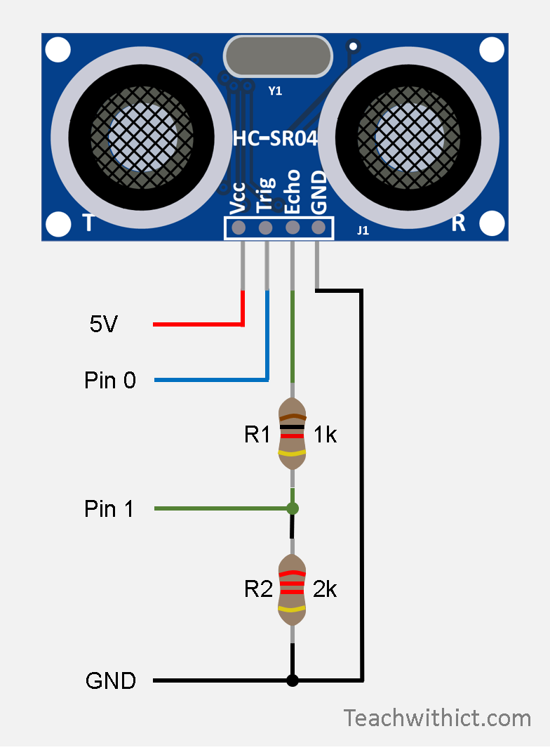
Creating the voltage divider
A voltage divider consists of two resistors (R1 and R2) connected in a series. In our case, we want to reduce the 5v being returned from the echo pin to a 3.3v – more suitable for our micro:bit.
What resistors you use largely depends on what resistors you have to hand however, without going into too much detail, as a rule of thumb, R2 should be exactly double the value of R1. For example, if we use a 1k ohm resistor for R1 we will need to use a 2k ohm resistor for R2.
|
Configuration
Our resistors need to be connected in a series. See image right. Whilst it is possible to achieve the above configuration using crocodile clips, I find it much easier to use a breadboard and jumper wires. See example below. |
|
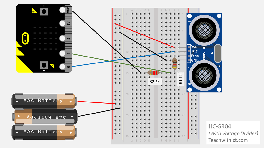
HC-SR04 ultrasonic sensor (5v) connected to a BBC micro:bit with voltage divider.
Frequently Asked Questions
Q1: What do I need to connect the HC-SR04 sensor to a micro:bit?
Q2: How does the ultrasonic sensor work?
Q3: How do I wire the HC-SR04 sensor to the micro:bit?
Q4: How can I protect my micro:bit from voltage damage?
- A1: You will need a BBC micro:bit, a micro USB cable, a battery pack with 2 or 3 AAA batteries, an HC-SR04 (5v) sensor, and 5 crocodile clip leads.
Q2: How does the ultrasonic sensor work?
- A2: It sends out a high-frequency sound wave and calculates the time it takes for the echo to return, determining the distance to an object.
Q3: How do I wire the HC-SR04 sensor to the micro:bit?
- A3: Connect Trig to Pin 0, Echo to Pin 1, GND to GND, and use a separate power source to provide 4.5V to the sensor.
Q4: How can I protect my micro:bit from voltage damage?
- A4: Use a voltage divider with two resistors to reduce the 5v signal from the echo pin to 3.3v, suitable for the micro:bit.